

രോഗി നിരീക്ഷണത്തിൽ ഇസിജി ലീഡ് വയറുകൾ അത്യാവശ്യ ഘടകങ്ങളാണ്, ഇത് ഇലക്ട്രോകാർഡിയോഗ്രാം (ഇസിജി) ഡാറ്റ കൃത്യമായി ശേഖരിക്കാൻ സഹായിക്കുന്നു. ഉൽപ്പന്ന വർഗ്ഗീകരണത്തെ അടിസ്ഥാനമാക്കിയുള്ള ഇസിജി ലീഡ് വയറുകളുടെ ഒരു ലളിതമായ ആമുഖം ഇതാ, അവയെ നന്നായി മനസ്സിലാക്കാൻ നിങ്ങളെ സഹായിക്കുന്നു.
ഉൽപ്പന്ന ഘടന അനുസരിച്ച് ഇസിജി കേബിളുകളുടെയും ലെഡ് വയറുകളുടെയും വർഗ്ഗീകരണം
1.സംയോജിത ഇസിജി കേബിളുകൾ
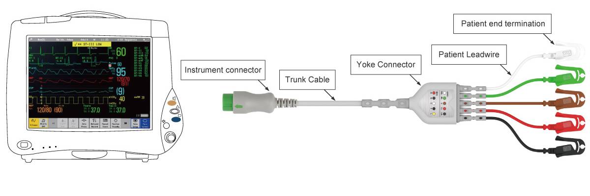
ദിസംയോജിത ഇസിജി കേബിളുകൾഇലക്ട്രോഡുകളും കേബിളുകളും വളരെയധികം സംയോജിപ്പിക്കുന്ന ഒരു നൂതന രൂപകൽപ്പനയാണ് ഇത് സ്വീകരിക്കുന്നത്, ഇന്റർമീഡിയറ്റ് ഘടകങ്ങളില്ലാതെ രോഗിയുടെ അറ്റത്ത് നിന്ന് മോണിറ്ററിലേക്ക് നേരിട്ട് കണക്ഷൻ സാധ്യമാക്കുന്നു. ഈ സ്ട്രീംലൈൻഡ് ഘടന ലേഔട്ട് ലളിതമാക്കുക മാത്രമല്ല, പരമ്പരാഗത സ്പ്ലിറ്റ്-ടൈപ്പ് സിസ്റ്റങ്ങളിൽ സാധാരണയായി കാണപ്പെടുന്ന ഒന്നിലധികം കണക്ടറുകളെ ഇല്ലാതാക്കുകയും ചെയ്യുന്നു. തൽഫലമായി, അനുചിതമായ കണക്ഷനുകളോ കോംഎൻടി കേടുപാടുകൾ മൂലമോ പരാജയപ്പെടാനുള്ള സാധ്യത ഇത് ഗണ്യമായി കുറയ്ക്കുന്നു, ഇത് രോഗി നിരീക്ഷണത്തിന് കൂടുതൽ സ്ഥിരതയുള്ളതും വിശ്വസനീയവുമായ പരിഹാരം നൽകുന്നു. നിങ്ങളുടെ റഫറൻസിനായി ഇന്റഗ്രേറ്റഡ് ഇസിജി കേബിളുകളുടെ ഉപയോഗം ഇനിപ്പറയുന്ന ഡയഗ്രം ചിത്രീകരിക്കുന്നു.
2.ഇസിജി ട്രങ്ക് കേബിളുകൾ
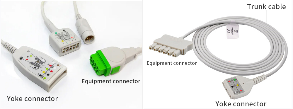
ദിഇസിജി ട്രങ്ക് കേബിളുകൾഇസിജി മോണിറ്ററിംഗ് സിസ്റ്റത്തിന്റെ ഒരു നിർണായക ഘടകമാണ്, അതിൽ മൂന്ന് ഭാഗങ്ങളുണ്ട്: ഉപകരണ കണക്റ്റർ, ട്രങ്ക് കേബിൾ, യോക്ക് കണക്റ്റർ.
3.ഇസിജി ലീഡ് വയറുകൾ
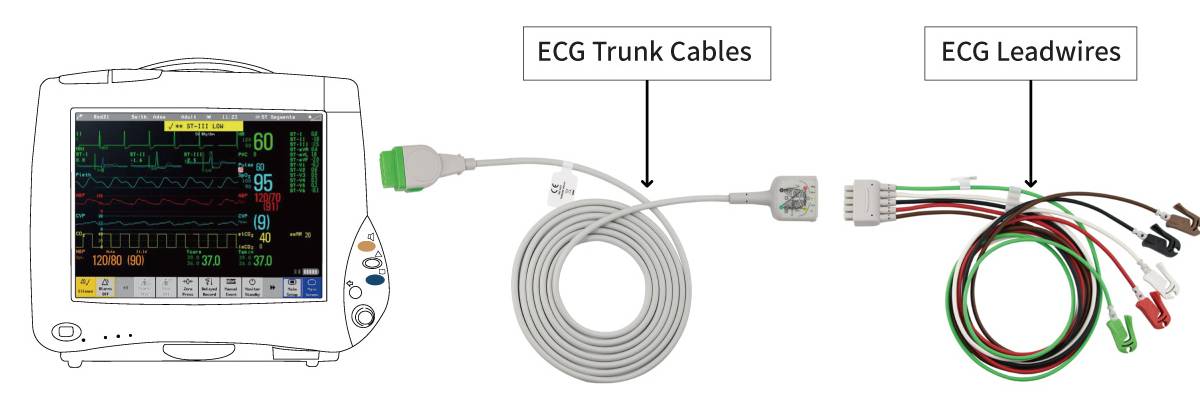
ഇസിജി ലെഡ് വയറുകൾECG ട്രങ്ക് കേബിളുകളുമായി സംയോജിച്ച് ഉപയോഗിക്കുന്നു. ഈ വേർതിരിക്കാവുന്ന രൂപകൽപ്പനയിൽ, കേടുപാടുകൾ സംഭവിച്ചാൽ ലെഡ് വയറുകൾ മാത്രമേ മാറ്റിസ്ഥാപിക്കേണ്ടതുള്ളൂ, അതേസമയം ട്രങ്ക് കേബിൾ ഉപയോഗയോഗ്യമായി തുടരുന്നു, ഇത് സംയോജിത ECG കേബിളുകളെ അപേക്ഷിച്ച് കുറഞ്ഞ അറ്റകുറ്റപ്പണി ചെലവ് നൽകുന്നു. കൂടാതെ, ECG ട്രങ്ക് കേബിളുകൾ ഇടയ്ക്കിടെ പ്ലഗ്ഗ് ചെയ്യുന്നതിനും അൺപ്ലഗ്ഗ് ചെയ്യുന്നതിനും വിധേയമാകില്ല, ഇത് അവയുടെ സേവന ആയുസ്സ് ഗണ്യമായി വർദ്ധിപ്പിക്കും.
ലെഡ് കൗണ്ട് അനുസരിച്ച് ഇസിജി കേബിളുകളുടെയും ലെഡ് വയറുകളുടെയും വർഗ്ഗീകരണം
-
3-ലെഡ് ഇസിജി കേബിളുകൾ


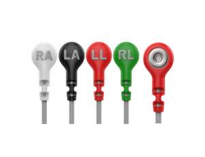
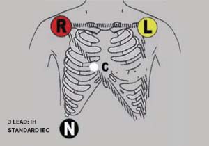
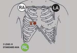
ഘടനാപരമായി,3-ലെഡ് ഇസിജി കേബിളുകൾമൂന്ന് ലെഡ് വയറുകൾ അടങ്ങിയിരിക്കുന്നു, ഓരോന്നും ഒരു പ്രത്യേക ഇലക്ട്രോഡുമായി ബന്ധിപ്പിച്ചിരിക്കുന്നു. ബയോഇലക്ട്രിക്കൽ സിഗ്നലുകൾ കണ്ടെത്തുന്നതിനായി ഈ ഇലക്ട്രോഡുകൾ രോഗിയുടെ ശരീരത്തിന്റെ വിവിധ ഭാഗങ്ങളിൽ സ്ഥാപിച്ചിരിക്കുന്നു. ക്ലിനിക്കൽ പ്രാക്ടീസിൽ, സാധാരണ ഇലക്ട്രോഡ് പ്ലേസ്മെന്റ് സൈറ്റുകളിൽ വലത് കൈ (RA), ഇടത് കൈ (LA), ഇടത് കാൽ (LL) എന്നിവ ഉൾപ്പെടുന്നു. ഈ കോൺഫിഗറേഷൻ ഹൃദയമിടിപ്പ് റെക്കോർഡുചെയ്യാൻ പ്രാപ്തമാക്കുന്നു.'ഒന്നിലധികം കോണുകളിൽ നിന്നുള്ള വൈദ്യുത പ്രവർത്തനത്തെ വിശകലനം ചെയ്യുന്നു, കൃത്യമായ മെഡിക്കൽ രോഗനിർണയത്തിന് ആവശ്യമായ ഡാറ്റ നൽകുന്നു.
-
5-ലീഡ് ഇസിജി കേബിളുകൾ


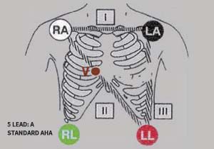
3-ലെഡ് ECG കേബിളുകളുമായി താരതമ്യപ്പെടുത്തുമ്പോൾ,5-ലെഡ് ഇസിജി കേബിളുകൾഅധിക ശരീരഘടനാപരമായ സൈറ്റുകളിൽ നിന്നുള്ള സിഗ്നലുകൾ പിടിച്ചെടുക്കുന്നതിലൂടെ കോൺഫിഗറേഷനുകൾ കൂടുതൽ സമഗ്രമായ കാർഡിയാക് ഇലക്ട്രിക്കൽ ഡാറ്റ നൽകുന്നു. ഇലക്ട്രോഡുകൾ സാധാരണയായി RA (വലത് കൈ), LA (ഇടത് കൈ), RL (വലത് കാൽ), LL (ഇടത് കാൽ), V (പ്രീകോർഡിയൽ/ചെസ്റ്റ് ലീഡ്) എന്നിവിടങ്ങളിൽ സ്ഥാപിക്കുന്നു, ഇത് മൾട്ടി-ഡൈമൻഷണൽ കാർഡിയാക് മോണിറ്ററിംഗ് പ്രാപ്തമാക്കുന്നു. ഈ മെച്ചപ്പെടുത്തിയ സജ്ജീകരണം ക്ലിനിക്കുകൾക്ക് ഹൃദയത്തെക്കുറിച്ച് കൃത്യവും പനോരമിക് ഉൾക്കാഴ്ചകളും നൽകുന്നു.'ഇലക്ട്രോഫിസിയോളജിക്കൽ സ്റ്റാറ്റസ്, കൂടുതൽ കൃത്യമായ രോഗനിർണയങ്ങളെയും വ്യക്തിഗത ചികിത്സാ തന്ത്രങ്ങളെയും പിന്തുണയ്ക്കുന്നു.
-
10-ലെഡ് അല്ലെങ്കിൽ 12-ലെഡ് ഇസിജി കേബിളുകൾ


ദി10-ലെഡ് / 12-ലെഡ് ഇസിജി കേബിൾഹൃദയ നിരീക്ഷണത്തിനുള്ള ഒരു സമഗ്ര രീതിയാണ്. ശരീരത്തിന്റെ പ്രത്യേക ഭാഗങ്ങളിൽ ഒന്നിലധികം ഇലക്ട്രോഡുകൾ സ്ഥാപിക്കുന്നതിലൂടെ, ഇത് ഹൃദയമിടിപ്പ് രേഖപ്പെടുത്തുന്നു.'വിവിധ കോണുകളിൽ നിന്നുള്ള വൈദ്യുത പ്രവർത്തനങ്ങളെ വിശകലനം ചെയ്യുന്നു, ഇത് ഹൃദ്രോഗങ്ങളുടെ കൂടുതൽ കൃത്യമായ രോഗനിർണയത്തിനും വിലയിരുത്തലിനും സഹായിക്കുന്ന വിശദമായ കാർഡിയാക് ഇലക്ട്രോഫിസിയോളജിക്കൽ വിവരങ്ങൾ ക്ലിനിക്കുകൾക്ക് നൽകുന്നു.
10-ലെഡ് അല്ലെങ്കിൽ 12-ലെഡ് ഇസിജി കേബിളുകളിൽ ഇനിപ്പറയുന്നവ ഉൾപ്പെടുന്നു:
(1)സ്റ്റാൻഡേർഡ് ലിംബ് ലീഡുകൾ (ലീഡുകൾ I, II, III):
വലതു കൈ (RA), ഇടതു കൈ (LA), ഇടതു കാൽ (LL) എന്നിവയിൽ സ്ഥാപിച്ചിരിക്കുന്ന ഇലക്ട്രോഡുകൾ ഉപയോഗിച്ച് ഈ ലീഡുകൾ അവയവങ്ങൾക്കിടയിലുള്ള പൊട്ടൻഷ്യൽ വ്യത്യാസങ്ങൾ അളക്കുന്നു. അവ ഹൃദയത്തെ പ്രതിഫലിപ്പിക്കുന്നു.'മുൻവശത്തെ തലത്തിലെ വൈദ്യുത പ്രവർത്തനം.
(2)ഓഗ്മെന്റഡ് യൂണിപോളാർ ലിംബ് ലീഡുകൾ (aVR, aVL, aVF):
ഈ ലീഡുകൾ നിർദ്ദിഷ്ട ഇലക്ട്രോഡ് കോൺഫിഗറേഷനുകൾ ഉപയോഗിച്ചാണ് ഉത്പാദിപ്പിക്കുന്നത്, കൂടാതെ ഹൃദയത്തിന്റെ കൂടുതൽ ദിശാസൂചന കാഴ്ചകൾ നൽകുന്നു.'മുൻവശത്തെ തലത്തിലെ വൈദ്യുത പ്രവർത്തനം:
- aVR: ഹൃദയത്തിന്റെ വലതു മുകൾ ഭാഗത്ത് ശ്രദ്ധ കേന്ദ്രീകരിച്ച് വലതു തോളിൽ നിന്ന് ഹൃദയത്തെ വീക്ഷിക്കുന്നു.
- aVL: ഇടത് തോളിൽ നിന്ന് ഹൃദയത്തെ വീക്ഷിക്കുന്നു, ഹൃദയത്തിന്റെ മുകൾ ഭാഗത്ത് ശ്രദ്ധ കേന്ദ്രീകരിക്കുന്നു.
- aVF: ഹൃദയത്തിന്റെ താഴത്തെ (താഴെ) ഭാഗത്ത് ശ്രദ്ധ കേന്ദ്രീകരിച്ച് പാദത്തിൽ നിന്ന് ഹൃദയത്തെ വീക്ഷിക്കുന്നു.
(3)പ്രീകോർഡിയൽ (നെഞ്ച്) ലീഡുകൾ
- ലീഡുകൾ V1–V6 നെഞ്ചിലെ പ്രത്യേക സ്ഥാനങ്ങളിൽ സ്ഥാപിക്കുകയും തിരശ്ചീന തലത്തിൽ വൈദ്യുത പ്രവർത്തനം രേഖപ്പെടുത്തുകയും ചെയ്യുന്നു:
- V1–V2: വലത് വെൻട്രിക്കിളിൽ നിന്നും ഇന്റർവെൻട്രിക്കുലാർ സെപ്തത്തിൽ നിന്നുമുള്ള പ്രവർത്തനം പ്രതിഫലിപ്പിക്കുക.
- V3–V4: ഇടത് വെൻട്രിക്കിളിന്റെ മുൻവശത്തെ ഭിത്തിയിൽ നിന്നുള്ള പ്രവർത്തനം പ്രതിഫലിപ്പിക്കുക, V4 അഗ്രത്തിന് സമീപം സ്ഥിതിചെയ്യുന്നു.
- V5–V6: ഇടത് വെൻട്രിക്കിളിന്റെ ലാറ്ററൽ ഭിത്തിയിൽ നിന്നുള്ള പ്രവർത്തനം പ്രതിഫലിപ്പിക്കുക.
(4)വലത് ചെസ്റ്റ് ലീഡുകൾ
ലീഡുകൾ V3R, V4R, V5R എന്നിവ വലതു നെഞ്ചിലും, മിററിംഗ് ലീഡുകൾ V3 മുതൽ V5 വരെ ഇടതുവശത്തും സ്ഥാപിച്ചിരിക്കുന്നു. ഈ ലീഡുകൾ വലത് വെൻട്രിക്കുലാർ പ്രവർത്തനത്തെയും വലതുവശത്തുള്ള മയോകാർഡിയൽ ഇൻഫ്രാക്ഷൻ അല്ലെങ്കിൽ ഹൈപ്പർട്രോഫി പോലുള്ള അസാധാരണത്വങ്ങളെയും പ്രത്യേകമായി വിലയിരുത്തുന്നു.
പേഷ്യന്റ് കണക്ടറിലെ ഇലക്ട്രോഡ് തരങ്ങൾ അനുസരിച്ചുള്ള വർഗ്ഗീകരണം
1.സ്നാപ്പ്-ടൈപ്പ് ഇസിജി ലീഡ് വയറുകൾ

ലെഡ് വയറുകളിൽ ഇരട്ട-വശങ്ങളുള്ള ത്രൂ-ഷീത്ത് ഡിസൈൻ ഉണ്ട്. കളർ-കോഡഡ് മാർക്കറുകൾ ഇഞ്ചക്ഷൻ-മോൾഡ് ചെയ്തിരിക്കുന്നു, ഇത് കാലക്രമേണ മങ്ങുകയോ തൊലി കളയുകയോ ചെയ്യാത്ത വ്യക്തമായ തിരിച്ചറിയൽ ഉറപ്പാക്കുന്നു. പൊടി-പ്രതിരോധശേഷിയുള്ള മെഷ് ടെയിൽ ഡിസൈൻ കേബിൾ വളയ്ക്കുന്നതിനും, ഈട് വർദ്ധിപ്പിക്കുന്നതിനും, വൃത്തിയാക്കാനുള്ള എളുപ്പത്തിനും, വളയുന്നതിനുള്ള പ്രതിരോധത്തിനും വിപുലീകൃത ബഫർ സോൺ നൽകുന്നു.
2.റൗണ്ട് സ്നാപ്പ് ഇസിജി ലീഡ്വയറുകൾ


- സൈഡ് ബട്ടണും വിഷ്വൽ കണക്ഷൻ ഡിസൈനും:ഡോക്ടർമാർക്ക് സുരക്ഷിതമായ ലോക്കിംഗ്, വിഷ്വൽ സ്ഥിരീകരണ സംവിധാനം നൽകുന്നു, വേഗതയേറിയതും കൂടുതൽ വിശ്വസനീയവുമായ ലീഡ് കണക്ഷനുകൾ പ്രാപ്തമാക്കുന്നു;ലെഡ് വിച്ഛേദനം മൂലമുണ്ടാകുന്ന തെറ്റായ അലാറങ്ങളുടെ അപകടസാധ്യത കുറയ്ക്കുമെന്ന് ക്ലിനിക്കലായി തെളിയിക്കപ്പെട്ടിട്ടുണ്ട്.
- പീൽ ചെയ്യാവുന്ന റിബൺ കേബിൾ ഡിസൈൻ:കേബിൾ കുരുക്ക് ഇല്ലാതാക്കുന്നു, സമയം ലാഭിക്കുന്നു, വർക്ക്ഫ്ലോ കാര്യക്ഷമത മെച്ചപ്പെടുത്തുന്നു; മികച്ച ഫിറ്റിനും സുഖത്തിനും വേണ്ടി രോഗിയുടെ ശരീര വലുപ്പത്തെ അടിസ്ഥാനമാക്കി ഇഷ്ടാനുസൃതമാക്കിയ ലെഡ് വേർതിരിക്കൽ അനുവദിക്കുന്നു.
- ഡബിൾ-ലെയർ ഫുള്ളി ഷീൽഡഡ് ലെഡ് വയറുകൾ:വൈദ്യുതകാന്തിക ഇടപെടലിനെതിരെ മികച്ച സംരക്ഷണം നൽകുന്നു, അതിനാൽ വിപുലമായ വൈദ്യുത ഉപകരണങ്ങൾ ഉള്ള പരിതസ്ഥിതികൾക്ക് ഇത് അനുയോജ്യമാകും.
3.ഗ്രാബർ-ടൈപ്പ് ഇസിജി ലീഡ് വയറുകൾ


ദിഗ്രാബർ-ടൈപ്പ് ഇസിജി ലെഡ് വയറുകൾസംയോജിത ഇഞ്ചക്ഷൻ മോൾഡിംഗ് പ്രക്രിയ ഉപയോഗിച്ചാണ് ഇവ നിർമ്മിക്കുന്നത്, ഇത് വൃത്തിയാക്കാൻ എളുപ്പമാക്കുന്നു, വാട്ടർപ്രൂഫ് ആണ്, തുള്ളികളെ പ്രതിരോധിക്കും. ഈ ഡിസൈൻ ഇലക്ട്രോഡുകളെ ഫലപ്രദമായി സംരക്ഷിക്കുന്നു, മികച്ച ചാലകതയും സ്ഥിരതയുള്ള സിഗ്നൽ ഏറ്റെടുക്കലും ഉറപ്പാക്കുന്നു. ഇലക്ട്രോഡ് ലേബലുകളുമായി പൊരുത്തപ്പെടുന്ന കളർ-കോഡഡ് കേബിളുകളുമായി ലെഡ് വയറുകൾ ജോടിയാക്കിയിരിക്കുന്നു, ഉയർന്ന ദൃശ്യപരതയും ഉപയോക്തൃ-സൗഹൃദ പ്രവർത്തനവും നൽകുന്നു.
4.4.0 വാഴപ്പഴവും 3.0 പിൻ ഇസിജി ലെഡ് വയറുകളും
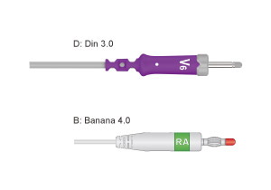

4.0 ബനാന, 3.0 പിൻ ഇസിജി ലെഡ് വയറുകൾക്ക് അനുയോജ്യതയും വിശ്വസനീയമായ സിഗ്നൽ ട്രാൻസ്മിഷനും ഉറപ്പാക്കുന്ന സ്റ്റാൻഡേർഡ് കണക്റ്റർ സ്പെസിഫിക്കേഷനുകൾ ഉണ്ട്. ഡയഗ്നോസ്റ്റിക് നടപടിക്രമങ്ങളും ഡൈനാമിക് ഇസിജി മോണിറ്ററിംഗും ഉൾപ്പെടെ വിവിധ ക്ലിനിക്കൽ ആപ്ലിക്കേഷനുകൾക്ക് അവ അനുയോജ്യമാണ്, കൃത്യമായ ഡാറ്റ ശേഖരണത്തിന് വിശ്വസനീയമായ പിന്തുണ നൽകുന്നു.
ഇസിജി ലെഡ് വയറുകൾ എങ്ങനെ ശരിയായി സ്ഥാപിക്കണം?
സ്റ്റാൻഡേർഡ് അനാട്ടമിക്കൽ ലാൻഡ്മാർക്കുകൾ അനുസരിച്ചാണ് ഇസിജി ലീഡ് വയറുകൾ സ്ഥാപിക്കേണ്ടത്. ശരിയായ സ്ഥാനം ഉറപ്പാക്കാൻ, വയറുകൾ സാധാരണയായി കളർ-കോഡ് ചെയ്തതും വ്യക്തമായി ലേബൽ ചെയ്തിരിക്കുന്നതുമാണ്, ഇത് ഓരോ ലീഡിനെയും തിരിച്ചറിയാനും വേർതിരിച്ചറിയാനും എളുപ്പമാക്കുന്നു.
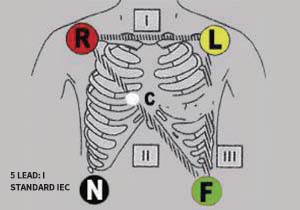
3 – ലീഡ്സ് ഇസിജി ലീഡ് വയറുകൾ | |||||||
| ഐ.ഇ.സി. | ആഹാ | ||||||
| ലീഡ് നാമം | ഇലക്ട്രോഡ് നിറം | ലീഡ് നാമം | ഇലക്ട്രോഡ് നിറം | ||||
| R | ചുവപ്പ് | RA | വെള്ള | ||||
| L | മഞ്ഞ | LA | കറുപ്പ് | ||||
| F | പച്ച | LL | ചുവപ്പ് | ||||
 |  | ||||||
5 – ലീഡ്സ് ഇസിജി ലെഡ് വയറുകൾ | |||||||
| ഐ.ഇ.സി. | ആഹാ | ||||||
| ലീഡ് നാമം | ഇലക്ട്രോഡ് നിറം | ലീഡ് നാമം | ഇലക്ട്രോഡ് നിറം | ||||
| R | ചുവപ്പ് | RA | വെള്ള | ||||
| L | മഞ്ഞ | LA | കറുപ്പ് | ||||
| F | പച്ച | LL | ചുവപ്പ് | ||||
| N | കറുപ്പ് | RL | പച്ച | ||||
| C | വെള്ള | V | തവിട്ട് | ||||
|  | ||||||
6-ലീഡുകൾ ഇസിജി ലെഡ് വയറുകൾ | |||||||
| ഐ.ഇ.സി. | ആഹാ | ||||||
| R | ചുവപ്പ് | RA | വെള്ള | ||||
| L | മഞ്ഞ | LA | കറുപ്പ് | ||||
| F | കറുപ്പ് | LL | ചുവപ്പ് | ||||
| N | പച്ച | RL | പച്ച | ||||
| C4 | നീല | V4 | തവിട്ട് | ||||
| C5 | ഓറഞ്ച് | V5 | കറുപ്പ് | ||||
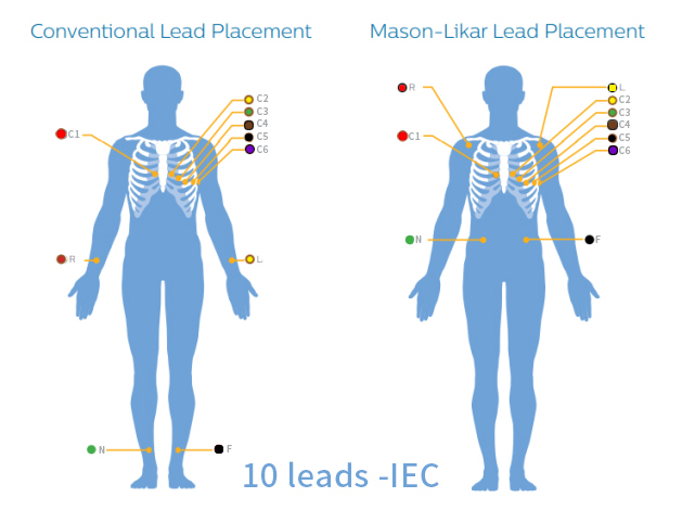
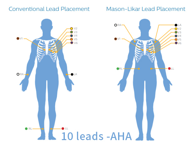
12-ലീഡുകൾ ഇസിജി ലെഡ് വയറുകൾ | |||||||
| ഐ.ഇ.സി. | ആഹാ | ||||||
| R | ചുവപ്പ് | RA | വെള്ള | ||||
| L | മഞ്ഞ | LA | കറുപ്പ് | ||||
| F | കറുപ്പ് | LL | ചുവപ്പ് | ||||
| N | പച്ച | RL | പച്ച | ||||
| C1 | ചുവപ്പ് | V1 | തവിട്ട് | ||||
| C2 | മഞ്ഞ | V2 | മഞ്ഞ | ||||
| C3 | പച്ച | V3 | പച്ച | ||||
| C4 | തവിട്ട് | V4 | നീല | ||||
| C5 | കറുപ്പ് | V5 | ഓറഞ്ച് | ||||
| C6 | പർപ്പിൾ | V6 | പർപ്പിൾ | ||||
 |  | ||||||
പോസ്റ്റ് സമയം: ജൂൺ-05-2025